Greening the skies
Researchers at KTH Mechanics have been working towards reducing greenhouse gas emissions by improving aircraft designs.
by Dan Henningson, Ardeshir Hanifi and Philipp Schlatter,
KTH Department of Mechanics
Global warming and concerns about greenhouse gases are major issues these days. While carbon offsets are one way to balance carbon emissions in the airline industry, Professor Dan Henningson and his team in the Department of Mechanics at the KTH Royal Institute of Technology and the Linné FLOW Centre – which includes Ardeshir Hanifi, Philipp Schlatter and a number of postdoctoral researchers and graduate students – are looking at ways to reduce fuel consumption (and hence the amount of carbon dioxide in aviation exhaust gases) by reducing the air resistance (or drag) on aeroplane wings.
To this end they have been conducting large-scale computer simulations of the airflow over aircraft wings to help understand what effects different wing shapes and different wing surfaces have on air resistance.
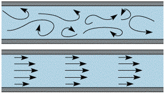
Philipp Schlatter explains that a significant portion of the drag on an aircraft is caused by what is referred to as the turbulent flow of air over the surface of the aircraft. To understand the difference between this turbulent flow (which causes a lot of the air resistance) and what we ideally want (which is known as laminar flow), think of water flowing in a twisting river bed where there are many stones and tree roots – then compare that to water flowing in a smooth straight canal. In the river, there will be lots of eddies and the water will rush back on itself when it flows towards a rock – in other words, the flow will be turbulent. In the canal however, the water flows relatively smoothly with no interruptions, which is more like laminar flow (as shown in the diagram below).
If you look at the next figure, which shows the results from one of their simulations of turbulence around a wing, you will see swirls in the colours next to the narrower part of the wing shape. These swirls indicate air turbulence.
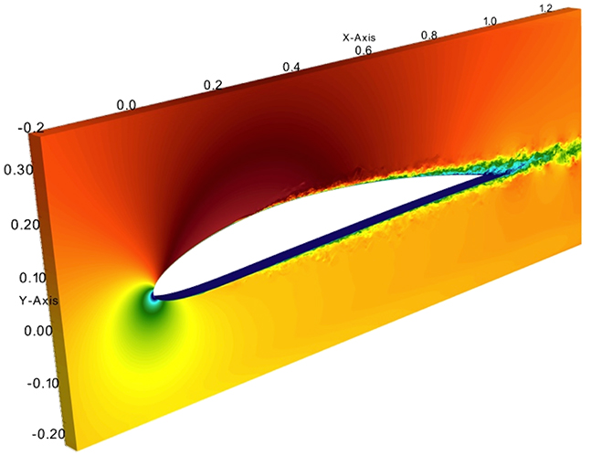
These results can be used to understand how varying the wing profile and surface can cause the airflow around the wing to change from a smooth laminar flow to a turbulent flow. (The more turbulent the flow is, the greater the air resistance is, and hence the harder the engines of the aircraft have to work and the more fuel they consume.) The resulting knowledge is vital for developing low-drag wing designs that reduce the area of turbulent airflow and thus decrease the plane’s fuel consumption and its impact on the environment.
As you can imagine, it takes a lot of equations and computations to make an accurate model of air resistance on even a small area of a wing. Using a total of about 10 billion points to represent the surface of the wing and a significant portion of the air around it, the group at KTH Mechanics has been able to simulate air turbulence on 50 cm of an aircraft wing at flight conditions. These results, which are shown in figure on the right, have been used to clarify some scaling laws (which can be used for improving models of turbulence which in turn allow cheaper development times). The results have also helped other researchers to calibrate some of the measurement probes that they use when building physical models and testing them in a wind tunnel. In the past, that was the only way to investigate the effects of changing the shape of a wing, or the material that it was made of. However it was, and still is, both time-consuming and costly as a means of testing various options for wing designs. Consequently, researchers are ultimately aiming to model the air currents around a whole aeroplane (although it is predicted that it will take another 20 or 30 years to reach the point where that can be done). As a step in that direction, the group at KTH Mechanics is now working on extending their simulations to cover a whole wing, which is something that no one has yet achieved. These computationally very intensive projects are supported both by the Swedish e-Science Research Centre (SeRC) and the Wallenberg Foundation.
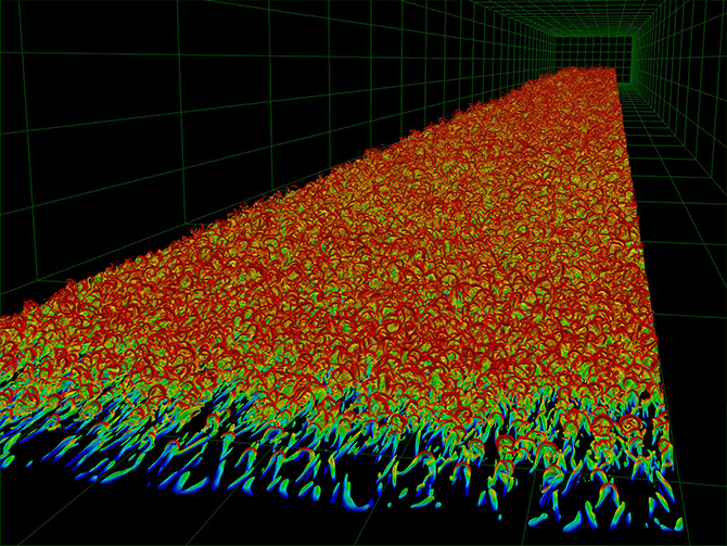
The canonical version of an aeroplane wing is the so-called flat-plate boundary layer. The figure shows a snapshot of the complex turbulent flow structures that appear around the surface of a wing, with the colour indicating the local velocity of the air. Just imagine all these turbulent worms of air being continuously generated while flying in an aeroplane! To make accurate predictions of the lift and drag forces on a wing, the researchers need to take all of these phenomena into account in their calculations.