This is not an easy one. You will need patience and soldering skills. Your result will probably vary from mine. So you have been warned before you proceed.
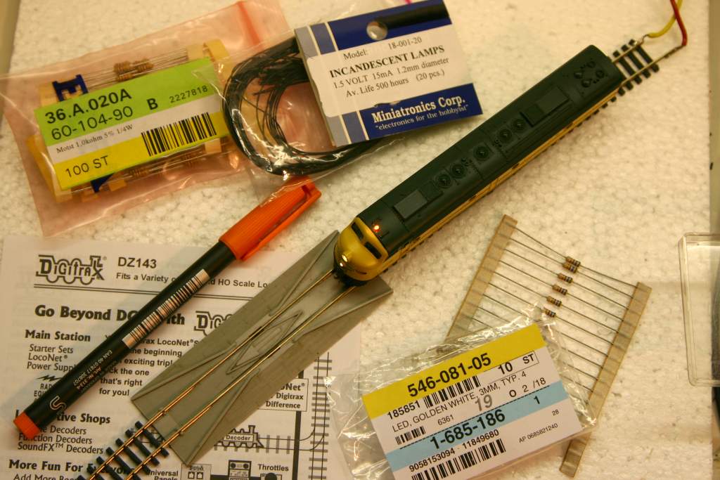
This is most of the material used for the conversion:
- The old Con-Cor E8
- Digitrax DZ143 decoder
- Resistors for the LEDs and light bulb
- LEDs
- Bulbs (i trashed one during work)
- Orange colored overhead pen
- Black, silver and metal colors
- M2 screws
- small screwdrivers
- flat metal file
- small triangular metal file
- 1.6mm drill, M2 tap
- small knive / blade
- pliers, tweezers
- soldering station with small tip, mine is 1mm
- solder (I like Weller L-Sn60PbCu2/zh)
- small brush
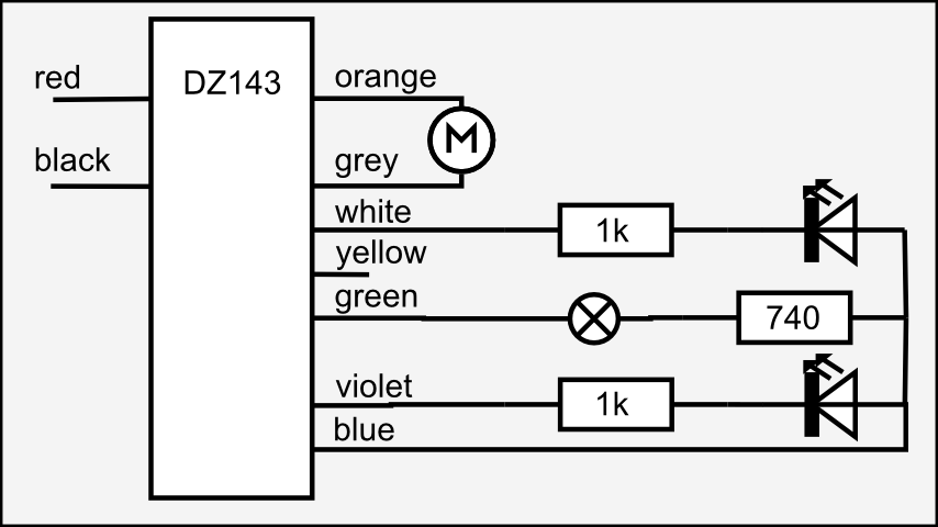
The schematics are straight forward. The resistror values were
determined by trial and error. After such an error the value for the
lamp was raised to 740 Ohms. This should be within the current limits
of the components. The white LEDs are very bright and do not need to
be run at their full current rating. Remember that the "red side" of
the pickup is the "orange side" of the motor. I usually use the
right/driver side for this. It may be smart to mark the sides of the
motor before disassembly.
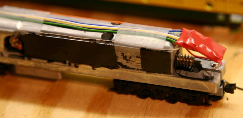
The biggest problem is how to fit everything inside. I disassembled everything and filed away metal from the following places: Top - file flat over whole area; Back - file 45 deg where all the cables leave the decoder; Sides - file a groove where the motor leads go down.
Inside the cab, you can see the anti-glare-though-shell paint which
consists of layers of silver and black paint. I have removed some of
the clear plasic window insert where it is not needed, too. This gives
more clearance for cables under the cab roof.
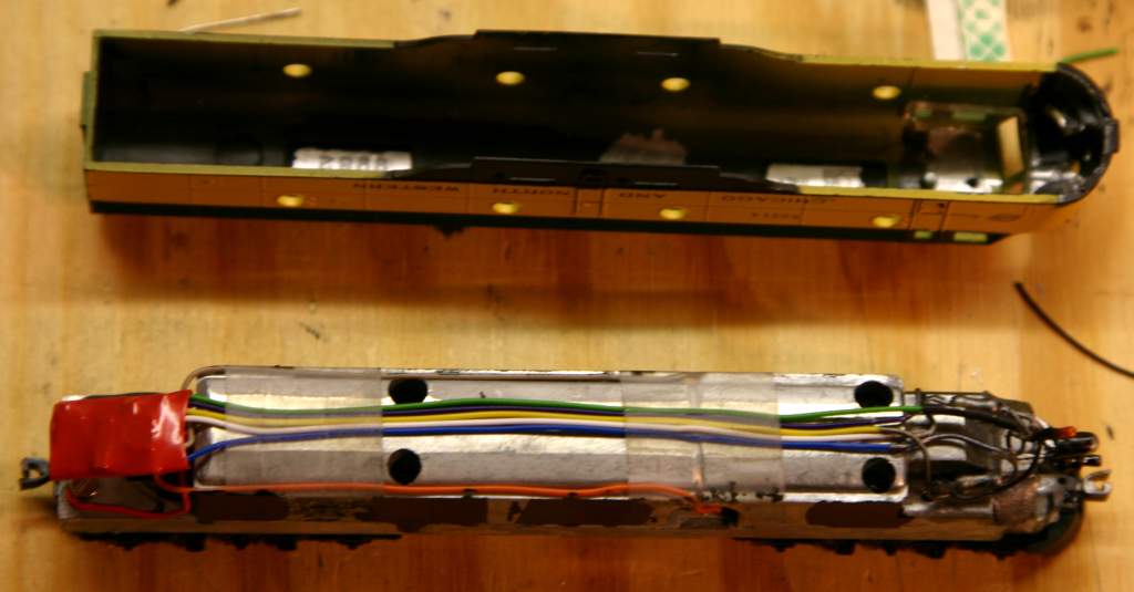
To feed the decoder from the split frame design, I drilled and tapped
two M2 holes into the overhanging rear end.
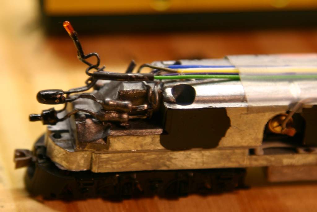
Fireman side of the cab: Here, you can see the two resistors for the LEDs. The LEDs were filed down to 2.9mm and 1.1mm diamater on a dremel-like tool. Do not forget eye protection when doing such work, the little buggers can get a quite impressive escape velocity. The chassis must be isolated from the LED and resistor leads. I used office tape underneat and then as everything is "in plain sight" in the cab, it was painted in some metal color. The color will hopefully serve as additional insulation.
The LEDs are all blackened with paint (first silver, then black) to
minimize stray light. Before, light was emerging through every crack
and window.
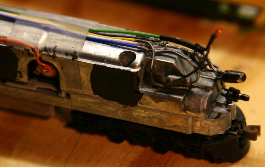
Driver side of the cab: The yellow cable was routed to the cab in case
of me going in for a rear light. But I doubt that will happen soon.
The resistor is for the flashing light. Because of the cramped space,
the bulb was wired first to the function output and then the resistor.
Normally I prefer the more safe "resistor on function output first"
approach as that is less harmful in case of short to chassis. On this
side, there is the "common" or "blue" connection for all lights, too.
After painting the metal visible through the portholes black, I
lowered the shell onto the body. That must be done slowly and
carefully, so that the lights end up in their openings. I ruined
one light bulb that way. The glass is sturdy, but the electrical
leads come of if you bend them too often or too hard.
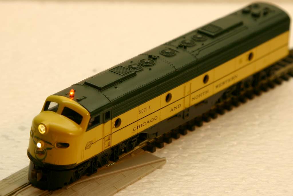
I programmed the decoder for the following effects:
- F0/white lead, lower headlight: Directional light, no effects
- F1/green lead, bulb: Effect non-directional gyralite CV51=0x20+0x07=0x27=39
- F2+F3 mapped to same output, violet lead: CV36=8, CV37=8
- Violet lead, top headlight, Effect directional mars light: CV52=0x00+0x02=2